Electrical circuit-interrupters
Electrical circuit-interrupters, such as AFCI’s (arc-fault circuit-interrupters) and GFCI’s (ground-fault circuit-interrupters), are devices required by the National Electrical Code (NEC) that are designed specifically to help prevent fires and electric shock. When installed as required, AFCIs and GFCIs significantly reduce accidents that naturally result in physical loss, electrical shock, and even death.
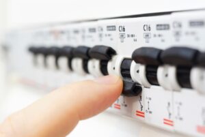
AFCIs (arc-fault circuit-interrupters)
AFCIs are required by the NEC to be installed within all dwelling units. Typically, they are special AFCI circuit breakers that can be found within your electrical panel or receptacles in the wall.
So, what do AFCIs do? AFCIs are designed to detect arcing electrical faults within your electrical system that may otherwise go unnoticed, until they potentially result in a fire. Arc-faults can be caused by things as innocent as putting a nail in the wall to hang a picture or plugging in an appliance with a defective electrical cord. If a nail makes contact with an electrical wire or a cord has a defect, arcing can happen, and is rarely ever seen. An AFCI device, however, will sense abnormal arcing on the electrical system and open the circuit when detected.
Key points about AFCIs:
All AFCIs should be installed by a qualified electrician.
Homes that were built prior to AFCI’s being required by the NEC, or homes built in states whose electrical codes do not follow the NEC arc-fault requirements, may not have arc-fault interrupters installed. While AFCI’s may not currently be installed in your home, ask a licensed electrician to install AFCI protection for your safety.
All AFCIs should be tested at initial installation and monthly, at minimum, thereafter to make sure they are working properly.
GFCIs (ground-fault circuit-interrupters)
GFCIs have been required by the NEC since 1971. Initially they were required for all outdoor receptacles, and bathrooms were added as a requirement in 1975. According to ESFI, the required areas for GFCI’s have grown since then based on the immense success they have had in reduction of electrocutions. Since their implementation in 1971, there has been an 83 percent drop in electrocutions, and a 95% drop in electrocutions caused specifically by consumer products.
How to Replace a Circuit Breaker
Circuit breakers last a long time so you should check your other options before deciding that issue is a faulty breaker. The breaker may need to be replaced if it trips very easily, doesn’t trip when it should, can’t be reset, is hot to the touch, or looks or smells burnt. If you can’t figure out the underlying issue or don’t feel knowledgeable or experienced enough to do the repair yourself, call a professional electrician. Working with electricity is dangerous, and it’s better to be safe than sorry.
When replacing a circuit breaker, you will need:
New circuit breaker (same brand, make, model and size as the one you’re removing)
Rubber mat or plywood to stand on (this insulates you against electrical shock)
Insulated flashlight or independent light source
Insulated screwdriver
Insulated wire strippers
Cable connectors to connect the circuit breaker to the main panel
Voltage tester
Here’s how to replace your circuit breaker:
Shut off the branch circuit breakers one at a time.
Shut off the main circuit breaker.
Test all the wires with a voltage tester to make sure they’re dead before proceeding.
Remove the panel cover.
Disconnect the wire of the breaker you’re removing from the load terminal.
Carefully pry out the old breaker, paying careful attention to how it’s positioned.
Insert the new breaker and push it into position.
Attach the circuit’s wire to the load terminal. Strip a bit of insulation off the wires, if necessary.
Inspect the panel for any other problems. Tighten any loose terminals.
Replace the panel cover.
Turn on the main breaker.
Turn on the branch breakers one by one.
Test the breakers with a voltage tester to make sure everything is in order
Fundamentals of Electricity
Branch Circuits
A branch circuit is defined as that part of an electric circuit extending beyond the last circuit breaker or fuse. The branch circuits start at the breaker box and extend to the electrical devices connected to the service. Branch circuits are the last part of the circuit supplying electrical devices. These circuits are classified in two different ways, according to the type of loads they serve or according to their current-carrying capacity.
General purpose branch circuits are 120 volts circuits used for supplying lighting fixtures and receptacle outlets for most small portable appliances. There are usually a number of general purpose branch circuits supplying lights and outlets in different rooms around a residence or commercial or industrial building.
Circuits rated for a maximum of 15 amps using 14 gauge wire were common in older homes but are no longer recommended in new installations. Circuits rated for a maximum of 20 amps using 12 gauge wire are recommended for general purpose branch circuits in modern electrical wiring systems.
Appliance branch circuits are 120 volts circuits used for supplying fixed electric equipment such as refrigerators, washers, and other large appliances and electrical devices. Appliance branch circuits do not supply any lighting fixtures. Appliance branch circuits can not exceed 20 amps.
Installed in permanent locations such as an electric range, a clothes dryer, or an air conditioner. These circuits usually lead directly from the distribution panel to the appliance and do not serve any other electrical devices. These circuits can be any amperage size.
An electrician’s guide on how to fix a tripped fuse
Any kind of major electrical fault around the house will need to be repaired by a professional electrician. However, that said, there are a few everyday electrical tasks that aren’t complicated, or dangerous, which you could attempt yourself. The most important thing to remember is to switch off and unplug whatever it is you need to work on so there’s no danger of a live current.
The first thing to do is find your main fuse box (these days called a consumer unit), which will be in the same place as your electricity meter. They’re often in the main hallway of a house, in a purpose-built cupboard. This is where the electricity in your house is controlled from, and it’s important that you know where to go and what to do if you need to turn off the mains electricity. It’s also helpful to remember where you left a torch too
In the case of loss of electric light or power
Your fuse box, or consumer unit, will either have fuses or trip switches. Modern electric circuits are fitted with a circuit breaker fuse system; if a fault develops, a switch is tripped and the circuit is broken. Older ones have fuse holders and when a fuse is blown it must be replaced or rewired.
If you experience problems with an old-fashioned fuse box, it might be sensible to install a replacement which conforms to current regulations for ease, safety and peace of mind. If you need assistance with any kind of electrical installation we would recommend calling out a qualified electrician.
Setting a trip switch
Open the cover on the consumer unit to see which switches have tripped to the OFF position. Put them back to the ON position. If tripping occurs again, it is probably being caused by a faulty appliance. You need to identify which circuit is affected and which appliance on that circuit is causing the problem.
What is an Electric Circuit?
the concept of electric potential difference was discussed. Electric potential is the amount of electric potential energy per unit of charge that would be possessed by a charged object if placed within an electric field at a given location. The concept of potential is a location-dependent quantity – it expresses the quantity of potential energy on a per charge basis such that it is independent on the amount of charge actually present on the object possessing the electric potential. Electric potential difference is simply the difference in electric potential between two different locations within an electric field
To illustrate the concept of electric potential difference and the nature of an electric circuit, consider the following situation. Suppose that there are two metal plates oriented parallel to each other and each being charged with an opposite type of charge – one being positive and the other being negative. This arrangement of charged plates would create an electric field in the region between the plates that is directed away from the positive plate and towards the negative plate
A positive test charge placed between the plates would move away from the positive plate and towards the negative plate. This movement of a positive test charge from the positive plate to the negative plate would occur without the need of energy input in the form of work; it would occur naturally and thus lower the potential energy of the charge. The positive plate would be the high potential location and the negative plate would be the low potential location. There would be a difference in electric potential between the two locations
Now suppose that the two oppositely charged plates are connected by a metal wire. What would happen? The wire serves as a sort of charge pipe through which charge can flow. Over the course of time, one could think of positive charges moving from the positive plate through the charge pipe (wire) to the negative plate. That is, positive charge would naturally move in the direction of the electric field that had been created by the arrangement of the two oppositely charged plates. As a positive charge leaves the upper plate, the plate would become less positively charged as illustrated in the animation at the right. As a positive charge reaches the negative plate, that plate would become less negatively charged
Over the course of time, the amount of positive and negative charge on the two plates would slowly diminish. Since the electric field depends upon the amount of charge present on the object creating the electric field, the electric field created by the two plates would gradually diminish in strength over the course of time. Eventually, the electric field between the plates would become so small that there would be no observable movement of charge between the two plates. The plates would ultimately lose their charge and reach the same electric potential. In the absence of an electric potential difference, there will be no charge flow.